Welcome to Your SmartBar

The SmartBar connects to you Model C or Raspberry Pi, and gives you a designed case and PCB to connect many sensors to both GPIO, I2C and 3.3 volt and 5 volts power rails.

Getting Started:

1.0 Connecting your SmartBar to your Model C, or Raspberry Pi.

The SmartBar comes with a black cable that will plug into the back of your SmartBar, on the rear left or rear right pins.  The eight pin header are both the same, so you can connect to either side of the Smart Bar.   On the rear of the Model C,  you have a black rubber cap, that can be removed to connect you Model C to your Smart Bar.   To connect with the proper orientation, you will need to have the white maker on the end of the cable facing the same direction.  Both have to be facing up, or both can be facing down.


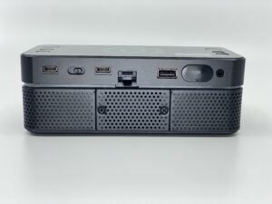
If you SmartBar is connected properly, you will see a bright blue LED lit on the right side of the SmartBar inside the case.  If the blue LED is lit,  you have the cable oriented in the right direction.

1.1 Smart Bar PCB

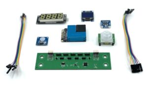
There are 5 I2C bus pins, which are marked on the PCB and there are 4 GPIO pin headers.  The next section will show how to wire the different style sensor to the header pins.


1.2 Smart Bar Case and Sensor Panels.

There are 5 Sensor panels that can be removed and swaped out, for the Model C,  we provide a series of standard panels, and also provide 3D.stl files for various other sensors.  You can 3D print sensor panels to add the sensors you are interesting in using in your SmartBar.  Much like PC expansion cards,  the SmartBar allows you to expand and add different combinations of sensors.


Panels include a touch panel, a horizontal OLED display Panel, a temperature sensor panel, and a motion panel. Other panels include one for a 120volt relay panel, a air quaility sensor and LED digital display Panel.